
Aunque no me haya mostrado activo en la escena de PCW, tengo un 8256 ampliado a 512K y con ganas de darle vidilla
Este ultimo mes le he estado dando vueltas al IDE para el CPC y entre otras cosas se me ha ocurrido que tambien se podria clavar al PCW.
Por un lado estaba el GIDE en el que parcialmente me baso, disponible con codigo para otras variantes del CP/M asi que ya de por si es un comienzo...
Por otro lado me he encontrado estas referencias que creo pueden ayudar a hacerlo "autoboot" en la pagina de John Elliott, en concreto en su PDF sobre hardware del PCW
He marcado en negrita dos cosas que me parecen interesantes:-Cirtech Gem
Physically, the Gem drive (at least the one I have) is a Seagate ST351A/X IDE drive,
jumpered for XT mode. If the jumpers are set for AT mode it is possible to connect it
to a modern PC and access the data at a sector level.
In XTA mode the drive has four registers, mimicking an XT hard drive controller.
On the PCW they can be found at ports 0A8h to 0ABh. The information below is
adapted from the Interrupt List entry for ports 0320h-0323h, which is where the registers appear on a PC. For full programming information, see the IBM PC technical
reference, pages 1-187 to 1-201.
0A8h Data register.
0A9h When read: controller status. When written: Reset controller.
0AAh When read: controller DIP switches. When written: Generate controller-select
pulse.
0ABh When written: DMA and interrupt mask (not used on the PCW)
In addition, the Gem interface has a 4k boot ROM. It would appear that on initial
startup, memory accesses with A7 reset go to the boot ROM, while memory accesses
with A7 set go to the PCW mainboard. So the 4k ROM is mapped into memory from
0000-007F, 0100-017F, 0200-027F, ..., 1F00-1F7F.
The first thing the GEM boot rom does is to mimic the normal PCW boot process
by copying the standard boot image (section 2) into memory. It does this by repeated
memory reads (from address 80h, so with A7 set) until the sequence D3 F8 [OUT
(0F8h),A] is encountered. Then it executes its own write to that port to switch to
normal execution, and copies itself into RAM.
While the ROM is paged in, all I/O port accesses use 16-bit I/O [OUT (C),A style],
with the top 8 bits of the address set to 80h. The first instruction after the boot ROM has been copied into RAM is IN A,(0A9h), with A=0. Presumably this I/O read, with
the top 8 bits of the address all 0, pages the boot ROM out.
-ASD PCWHD10 / PCWHD20
I haven’t seen one of these drives, so this information comes from disassembling the
driver (ASD.FID). The drive uses an ATA interface, and appears to make 8-bit transfers.
The registers are:
0A0h Data
0A1h Error / Features
0A2h Sector count
0A3h Sector number
0A4h Cylinder low
0A5h Cylinder high
0A6h Drive / Head
0A7h Status / Command
The review in ’8000 Plus’ says that the ASD drive can have 1-6 partitions, but the
driver I have doesn’t support this.
-Por un lado el primer interfaz, el Cirtech Gem, permite inyectar codigo de arranque en lugar del interno, por el mismo procedimiento. La clave parece estar en la señal A7
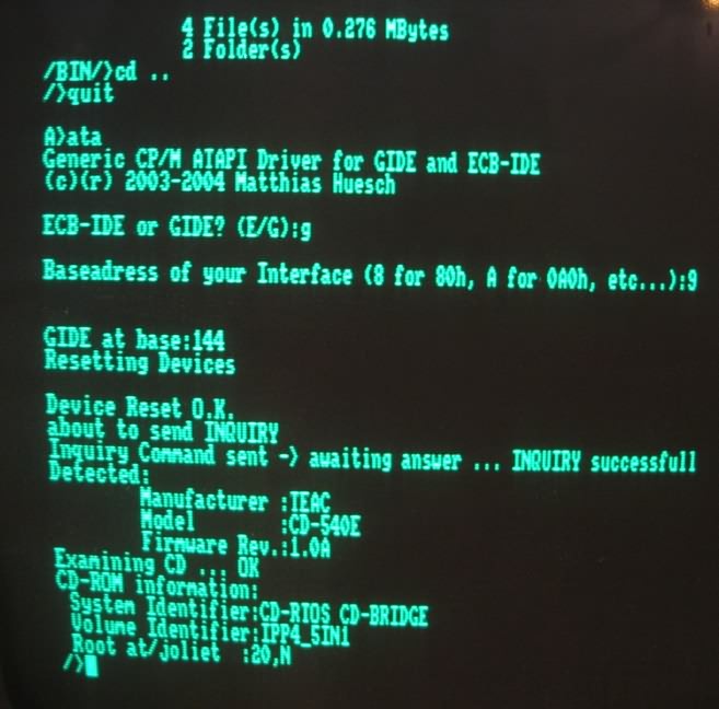
-El segundo dispone de un driver ASD.FID que permite acceder de identica manera que el IDE mio, puertos iguales al IDE/AT. Solo habria que reubicar los puertos para que funcione con el interfaz tal y como esta concevido ahora.
Mis batallitas con el IDE estan mas o menos explicadas y documentadas en el hilo correspondiente al hardware de CPC, con los diseños en proteus, fuentes de las GAL, etc, aparte he hecho publica una version "directa al BUS" para CPC hoy mismo: http://www.cpcwiki.eu/forum/amstrad-cpc ... /#msg51978
Como lo veis, apetitoso? factible? Al menos para darle un poco vueltas al tema como concepto, y mas adelante cuando madure la idea al turron!!


